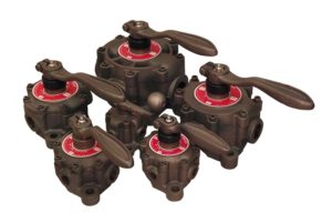
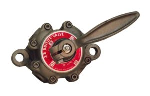
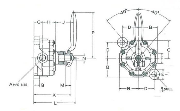
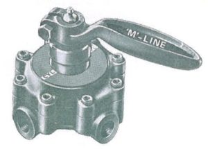
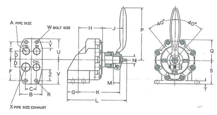
COLUMN MOUNT Unitite Valves
Unitite Valves of this model are used in remote control installations where it is desirable to provide support in addition to that given by the piping.
| DIMENSIONS OF COLUMN MOUNT UNITITE VALVES | |||||
|---|---|---|---|---|---|
| Dimension on Dwg. | Valve # (Air or Hydraulic) | ||||
| 135018 | 135019 | 135020 | 135008 | 135009 | |
| A | 3/8 | 1/2 | 3/4 | 1 | 1 1/4 |
| B | 2.06 | 2.31 | 2.75 | 3.25 | 3.75 |
| C | 1.94 | 2.06 | 2.50 | 2.88 | 3.31 |
| D | 1.75 | 1.88 | 2.12 | 2.50 | 2.75 |
| E | 1.12 | 1.12 | 1.12 | 1.12 | 1.25 |
| F | 1.12 | 1.31 | 1.62 | 1.88 | 2.50 |
| G | 0.94 | 0.94 | 1.12 | 1.50 | 1.25 |
| H | 1.44 | 1.62 | 1.69 | 2.00 | 2.50 |
| J | 2.00 | 2.19 | 2.38 | 2.38 | 2.38 |
| K | 4.12 | 4.25 | 4.81 | 5.50 | 6.12 |
| L | 4.75 | 4.88 | 5.44 | 6.12 | 6.75 |
| M | 0.62 | 0.62 | 0.81 | 0.81 | 0.81 |
| N | 0.62 | 0.75 | 0.88 | 0.88 | 0.88 |
| P | 5.00 | 6.00 | 7.75 | 7.75 | 7.75 |
| Q | 0.62 | 0.75 | 0.75 | 0.88 | 0.88 |
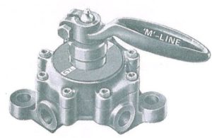
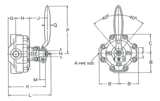
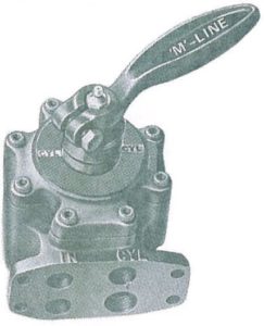
STANDARD MOUNT Unitite Valves
This Unitite Valve model is used in installations where the valve is mounted on the cylinder or where it can be amply supported by the piping.
| DIMENSIONS OF STANDARD MOUNT UNITITE VALVES | |||||
|---|---|---|---|---|---|
| Dimension on Dwg. | Valve # (Air or Hydraulic) | ||||
| 135015 | 135016 | 135017 | 135003 | 135004 | |
| A | 3/8 | 1/2 | 3/4 | 1 | 1 1/4 |
| B | 2.06 | 2.31 | 2.75 | 3.25 | 3.75 |
| C | 1.31 | 2.06 | 2.5 | 2.88 | 3.31 |
| D | 1.38 | 1.5 | 1.62 | 1.62 | 1.62 |
| E | 0.75 | 0.88 | 1 | 1 | 1 |
| F | 1.12 | 1.31 | 1.62 | 1.88 | 2.5 |
| G | 0.81 | 0.81 | 1 | 1.25 | 1.5 |
| H | 1.44 | 1.62 | 1.69 | 2 | 2.5 |
| J | 2 | 2.19 | 2.38 | 2.38 | 2.38 |
| K | 4 | 4.12 | 4.69 | 5.25 | 6 |
| L | 4.62 | 4.75 | 5.31 | 5.88 | 6.62 |
| M | 0.62 | 0.62 | 0.81 | 0.81 | 0.81 |
| N | 0.62 | 0.75 | 0.88 | 0.88 | 0.88 |
| P | 5 | 6 | 7.75 | 7.75 | 7.75 |
| Q | 0.62 | 0.75 | 0.75 | 0.75 | 0.75 |
MANIFOLD MOUNT Unitite Valves
For installations where several valves must be grouped closely together – all ports are in the mounting face of the valve. Necessary piping to and from the valves does not interfere with piping to adjoining valves. Intake and exhaust openings may be conveniently connected to single supply or exhaust pipes – or to a manifold or pulpit block.
| DIMENSIONS OF MANIFOLD UNITITE VALVES | |||||
|---|---|---|---|---|---|
| Dimension on Dwg. | Valve # (Air or Hydraulic) | ||||
| 135021 | 135022 | 135023 | 135013 | 135014 | |
| A | 3/8 | 1/2 | 3/4 | 1 | 1 1/4 |
| B | 2.12 | 2.75 | 3.25 | 4.12 | 4.75 |
| C | 1.00 | 1.38 | 1.50 | 2.00 | 2.25 |
| D | 0.75 | 1.00 | 1.12 | 1.50 | 1.50 |
| E | 1.62 | 2.12 | 2.38 | 3.06 | 3.19 |
| F | 2.06 | 2.62 | 3.00 | 3.75 | 3.94 |
| G | 1.06 | 1.38 | 1.62 | 2.06 | 2.38 |
| H | 2.25 | 2.62 | 3.06 | 3.75 | 4.06 |
| J | 2.00 | 2.19 | 2.38 | 2.38 | 2.38 |
| K | 4.00 | 4.31 | 5.06 | 5.75 | 6.06 |
| L | 5.69 | 6.31 | 7.31 | 8.44 | 9.06 |
| M | 0.62 | 0.62 | 0.81 | 0.81 | 0.81 |
| N | 0.62 | 0.75 | 0.88 | 0.88 | 0.88 |
| P | 5.00 | 6.00 | 7.75 | 7.75 | 7.75 |
| Q | 1.94 | 2.06 | 2.31 | 2.88 | 3.38 |
| R | 0.31 | 0.44 | 0.50 | 0.56 | 0.56 |
| S | 2.25 | 2.50 | 3.00 | 3.25 | 4.00 |
| T | 0.31 | 0.38 | 0.50 | 0.56 | 0.62 |
| U | 1.94 | 2.56 | 2.88 | 3.62 | 3.75 |
| V | 2.38 | 3.06 | 3.50 | 4.31 | 4.50 |
| W | 0.31 | 0.38 | 0.44 | 0.50 | 0.50 |
| X | 0.50 | 0.75 | 1.00 | 1.25 | 1.50 |
| Y | 0.62 | 1.12 | 1.25 | 1.56 | 1.69 |
| Z | 1.00 | 1.62 | 1.88 | 2.25 | 2.44 |
Fluid Dynamics is a Stocking Distributor for Unitite Valves.
